Description
Manual Description:
Number of Pages: 63
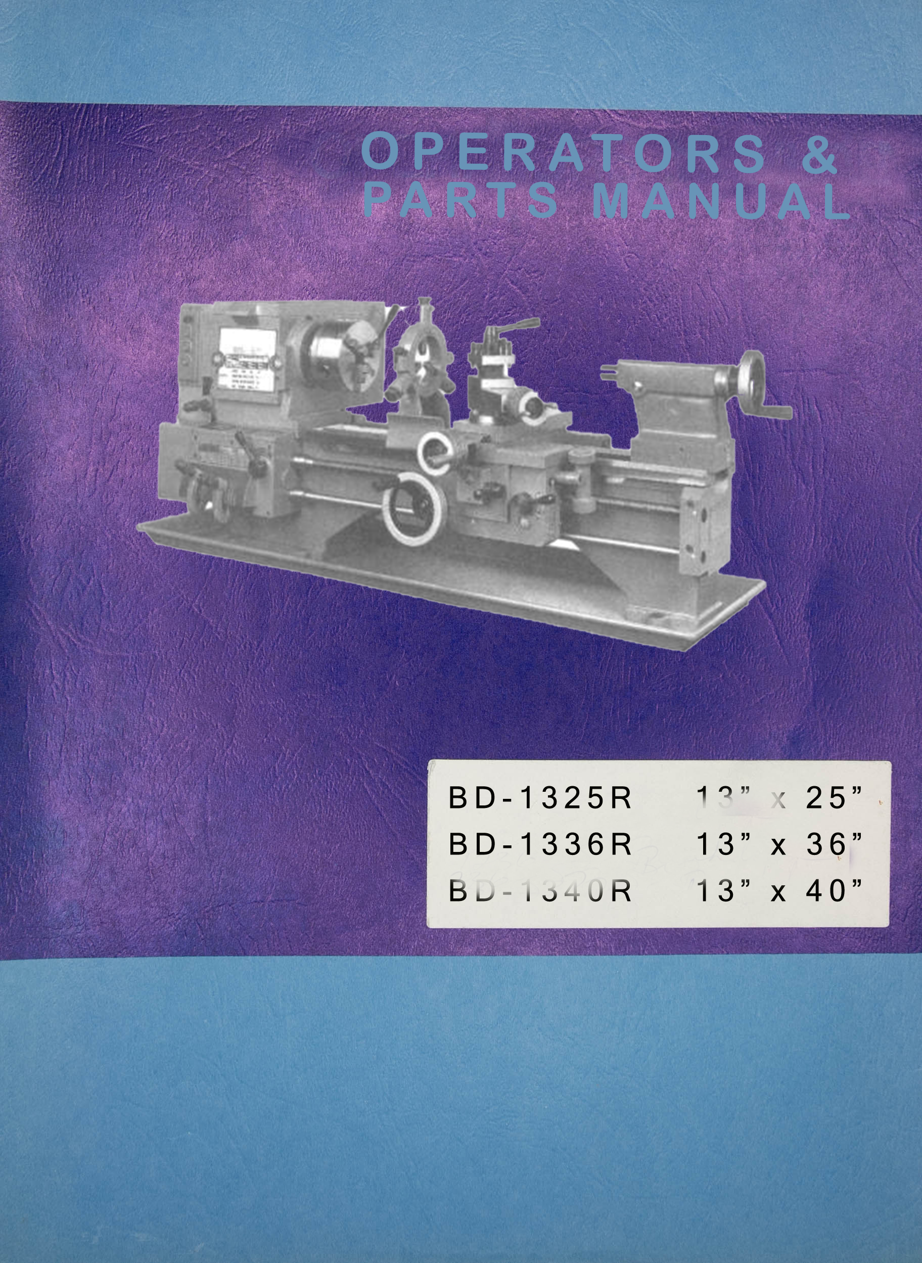
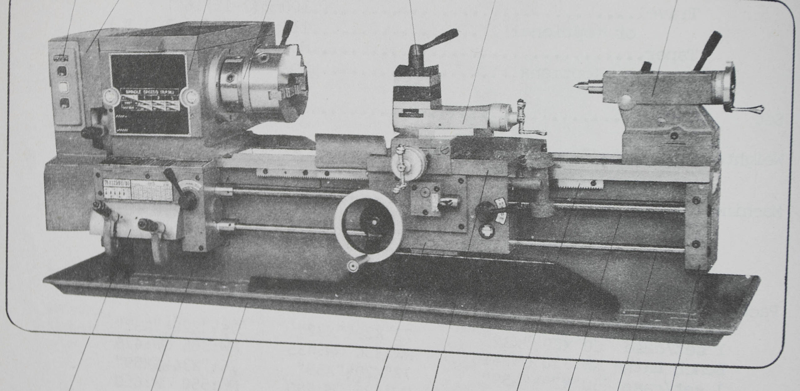
This is a reproduction, not a photocopy, of a Asian 13×25 13×36 13×40 13×45 Metal Lathe Instructions and Parts Manual. This machine is manufactured in Asia and has been sold under many different names including: JET, Grizzly, Enco 110-2031, Sharp, MSC, etc… This manual contains information on setup, lubrication, maintenance, and controls as well as a complete parts list and exploded views and adjustments. For an Asian manual this is put together well, and it covers a lot more than usual.
Known Models:
Enco 110-2031
BD-1325R
BD-1336R
BD-1340R
Paykel Engineering, TY-1340BH
Sharp 1340CU
JET 1240PY
Specifications:
Capacity & Dimensions
Swing
Over bed………………………………..330mm(13″)
Over cross slide…………………….198mm(7-25/32″)
In gap Diameter (optional)…………….476mm(18-3/4″)
Length (optional)………………….146mm(5-3/4″min.)
Center
Height…………………………………166mm(61/2)
Admits between (BD-1325R)…….628mm(24-23/32″)
(BD-1336R)………….915nm(36″)
(BD-134OR)…….1035rrm(40-3/4″)
Bed Width…………………………187mm(7-3/8″)
Length (BD-1325R)………….248mm(49-l/8″)
(CBD-1336R)…..1535rrm(60-3/8″)
(BD-1340R)…….1655mm(65-l/8″)
Height…………………………….290mm(ll-13/32″)
Drive……………………..Motor via belts & pulley
Motor For main spindle……2HP, 3ph or 2HP, or lHP, lph
Headstock
Spindle Bore………………………39mm(l-17/32″)
Nose…………………A.S.A. M. TYPE, 21/4-8 T.P.I.
or (optional)…………………Dl-4″ ASA std.
Taper in nose…………………………..No.5 Morse
in sleeve……………………..No.3 Morse
Speeds Number……………………………….12
Range…………………60-1240 r.p.m.
Carriage & Compound
Cross slide Width……………………118mm(4-5/8″)
Travel ……………160mm(6-5/16″)
Compound rest Width……………………….76mm(3″)
Travel………68mm (2-11/16″)
Lead screw Diameter……………………22mm(7/8″)
Thread…….8 T.P.I, or 3mm pitch
Feed rod Diameter…………………….19mm(3/4″)
Tailstock Quill
Taper………………………………….No.2 Morse
or (optional)………………………….No.3 Morse
Contents:
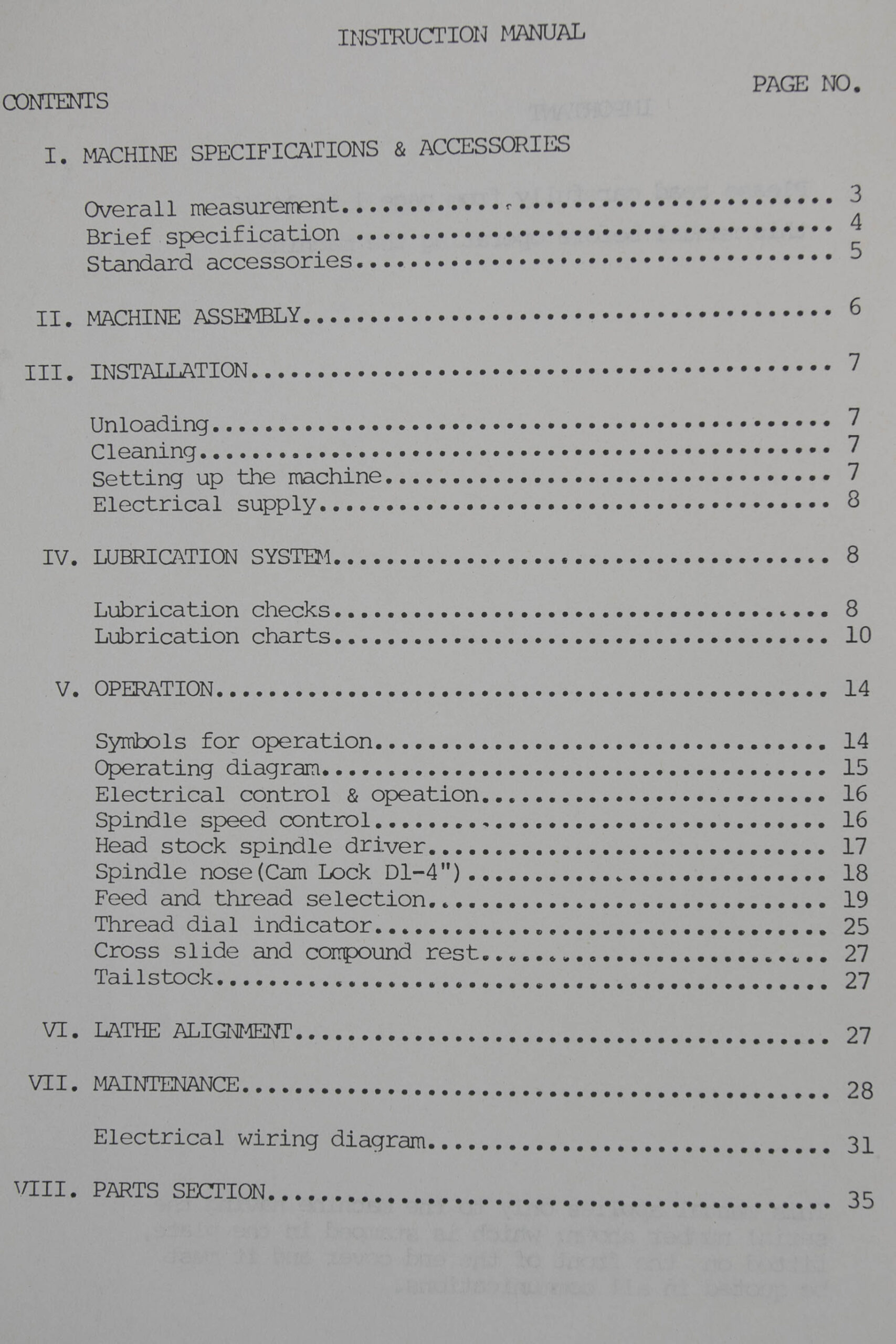
Overall measurement……………………………..3
Brief specification……………………………..4
Standard accessories…………………………….5
II. MACHINE ASSEMBLY…………………………….6
III. INSTALLATION……………………………….7
Unloading………………………………………7
Cleaning……………………………………….7
Setting up the machine…………………………..7
Electrical supply……………………………….8
IV. LUBRICATION SYSTEM…………………………..8
Lubrication checks………………………………8
Lubrication charts……………………………..10
V. OPERATION…………………………………..14
Symbols for operation…………………………..14
Operating diagram………………………………15
Electrical control & operation…………………..16
Spindle speed control…………………………..16
Head stock spindle driver……………………….17
Spindle nose (Cam Lock Dl-4″)……………………18
Feed and thread selection……………………….19
Thread dial indicator…………………………..25
Cross slide and compound rest……………………27
Tailstock……………………………………..27
VI. LATHE ALIGNMENT…………………………….27
VII. MAINTENANCE……………………………….28
Electrical 1 wiring diagram……………………..31
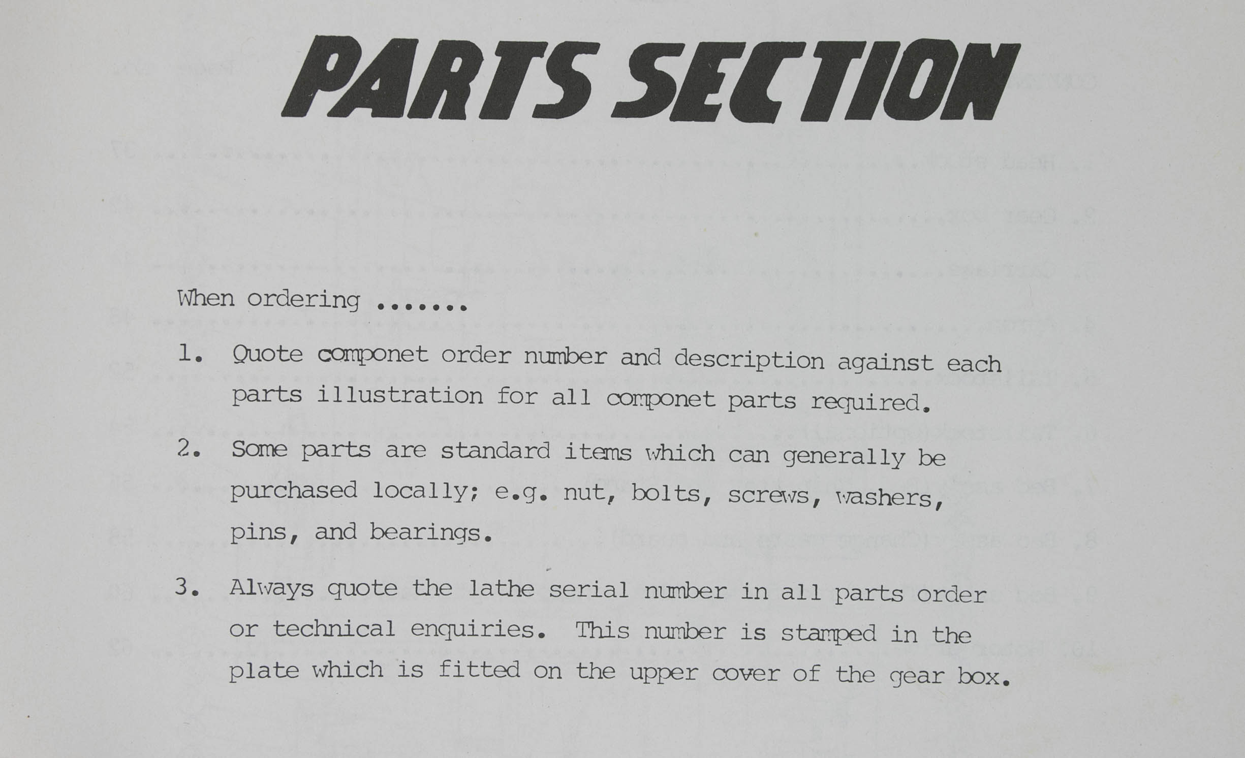
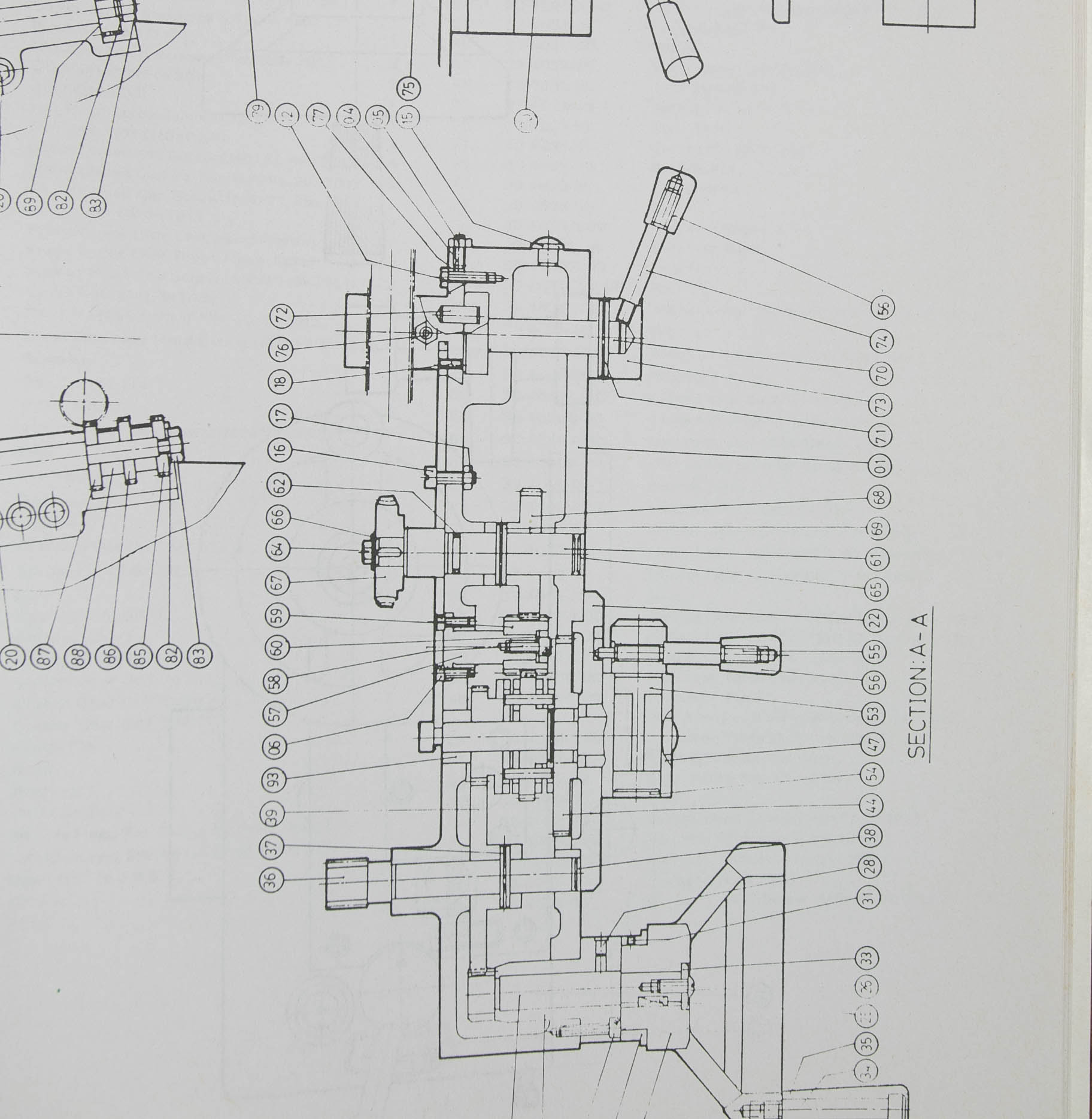
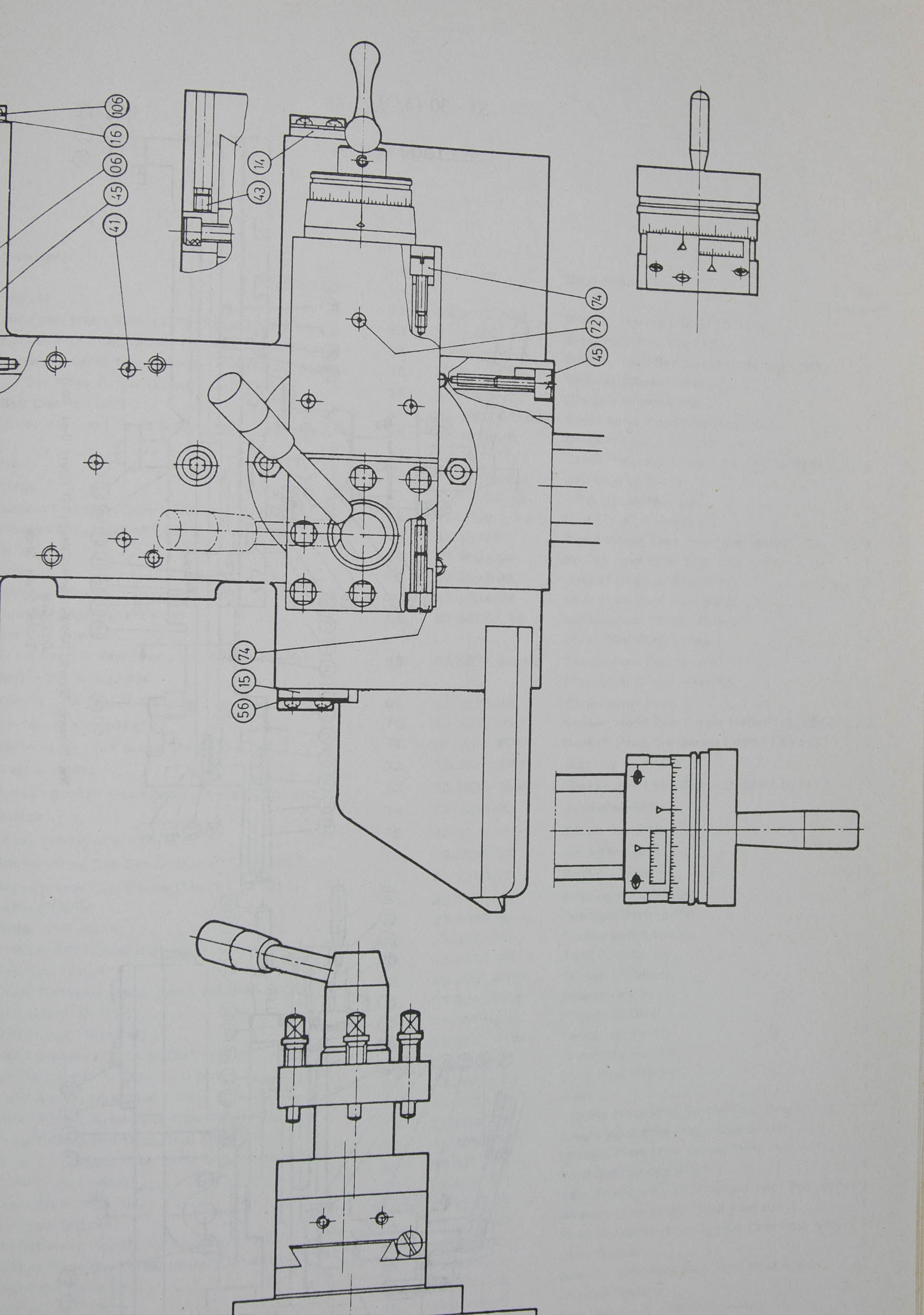
VIII. PARTS SECTION…………………………….35
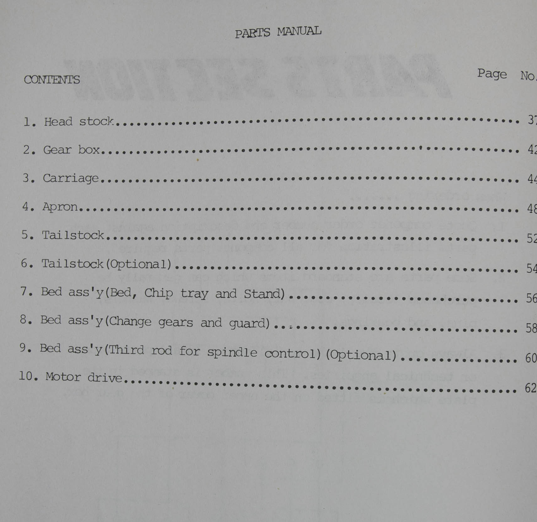
Head stock…………………………………….37
Gear box………………………………………42
Carriage………………………………………44
Apron…………………………………………48
Tailstock……………………………………..52
Tailstock (Optional)……………………………54
Bed ass’y(Bed, Chip tray and Stand)………………56
Bed ass’y (Change gears and guard)……………….58
Bed ass’y(Third rod for spindle control)………….60
Motor drive……………………………………62

Reviews
There are no reviews yet.