Description
Manual Description:
Number of Pages: 78
Operations, Maintenance, Lubrication and PARTS.
PLUS the 4 Page cut sheet

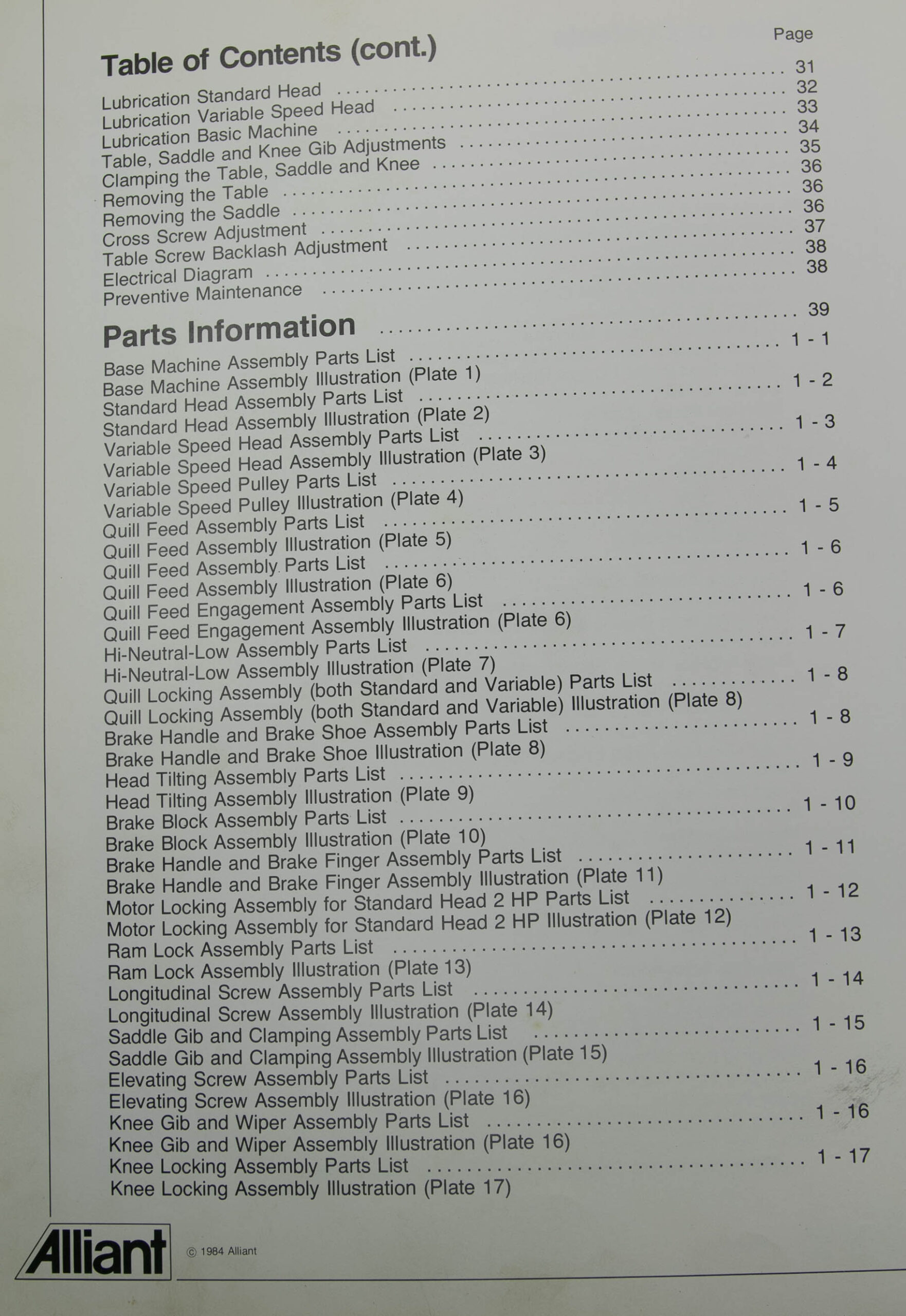
Contents:
Foreword.................................................................5

Warranty.................................................................6

Safety...................................................................7

RT 2S Main Machine Features............................................8-9

RT 2V Main Machine Features..........................................10-11

Basic Machine Dimensions................................................12

Floor Plan..............................................................13

Standard Head Dimensions................................................14

Variable Speed Head Dimensions..........................................14

Machine Specifications..................................................15

Uncrating and Installation..............................................16

Remove Machine from Crate...............................................16

Check for Shortages.....................................................16

Clean and Lubricate Machine.............................................16

Place Machine on a Solid Foundation.....................................16

Bring Head to the Upright Position......................................16

Level the Machine.......................................................17

Connect Power Supply....................................................17

Proper Method for Lifting Machine.......................................17

Head Alignment..........................................................18

Align Y Axis............................................................18

Align X Axis............................................................18

Standard Head...........................................................19

Swivel Belt Housing.....................................................20

Spindle Brake...........................................................20

Changing Spindle Speed..................................................20

Changing from Direct Drive to Back-gear.................................20

Changing from Back-gear to Direct Drive.................................20

Belt Replacement........................................................21

Replacing the Brake Block on the Standard Milling Head..................21

Variable Speed Head.....................................................22

High and Low Range Switch...............................................23

High-Neutral-Low Lever..................................................23

Automatic Quill Feed Engagement.........................................23

Feed Rate Selector......................................................23

Feed Reversing Knob.....................................................23

Quill Depth Stop........................................................23

Micrometer Depth Control................................................23

Quill Locking Lever.....................................................23

Handwheel Feed Control..................................................24

Automatic Feed..........................................................24

Spindle Brake...........................................................25

Collet..................................................................25

Feed Trip Adjustment....................................................26

Collet Aligning Screw Replacement.......................................27

Swivel Belt Housing.....................................................28

Changing Spindle Speed..................................................28

Changing from Direct Drive to Back-gear Drive...........................28

Changing from Back-gear Drive to Direct Drive...........................28

Motor Removal...........................................................28

Timing Belt Replacement.................................................29

Drive Belt Replacement..................................................29

Replacing the Brake Shoes on the Variable Speed Head....................30

Lubrication Standard Head...............................................31

Lubrication Variable Speed Head.........................................32

Lubrication Basic Machine...............................................33

Table, Saddle and Knee Gib Adjustments..................................34

Clamping the Table, Saddle and Knee.....................................35

Removing the Table......................................................36

Removing the Saddle.....................................................36

Longitudinal Screw Adjustment...........................................36

Cross Screw Backlash Adjustment.........................................37

Electrical Diagram......................................................38

Preventive Maintenance..................................................38

Parts Information.......................................................39

Base Machine Assembly Parts List.......................................1-1

Base Machine Assembly Illustration

(Plate 1

Standard Head Assembly Parts List......................................1-2

Standard Head Assembly Illustration

(Plate 2

Variable Speed Head Assembly Parts List................................1-3

Variable Speed Head Assembly Illustration

(Plate 3

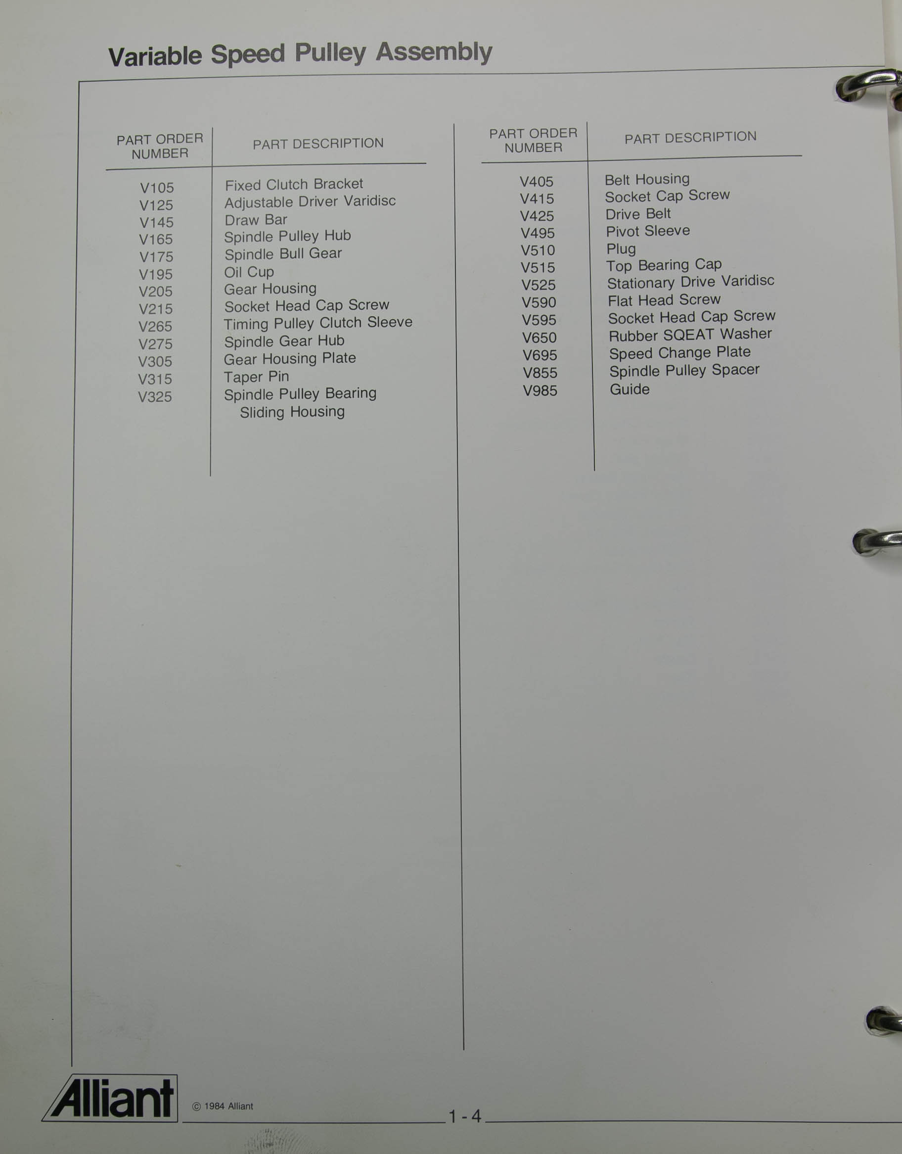
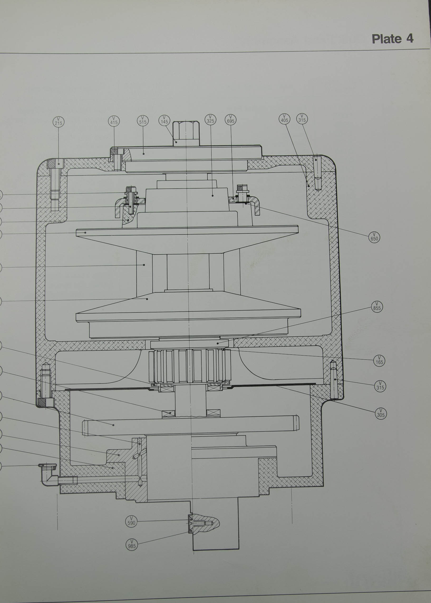
Variable Speed Pulley Parts List.......................................1-4

Variable Speed Pulley Illustration

(Plate 4

Quill Feed Assembly Parts List.........................................1-5

Quill Feed Assembly Illustration

(Plate 5

Quill Feed Assembly Parts List.........................................1-6

Quill Feed Assembly Illustration

(Plate 6

Quill Feed Engagement Assembly Parts List..............................1-6

Quill Feed Engagement Assembly Illustration

(Plate 6

Hi-Neutral-Low Assembly Parts List.....................................1-7

Hi-Neutral-Low Assembly Illustration

(Plate 7)

Quill Locking Assembly (both Standard and Variable) Parts List.........1-8

Quill Locking Assembly (both Standard and Variable) Illustration

(Plate 8)

Brake Handle and Brake Shoe Assembly Parts List........................1-8

Brake Handle and Brake Shoe Illustration

(Plate 8)

Head Tilting Assembly Parts List.......................................1-9

Head Tilting Assembly Illustration

(Plate 9)

Brake Block Assembly Parts List.......................................1-10

Brake Block Assembly Illustration

(Plate 10)

Brake Handle and Brake Finger Assembly Parts List.....................1-11

Brake Handle and Brake Finger Assembly Illustration

(Plate 11)

Motor Locking Assembly for Standard Head 2 HP Parts List..............1-12

Motor Locking Assembly for Standard Head 2 HP Illustration

(Plate 12)

Ram Lock Assembly Parts List..........................................1-13

Ram Lock Assembly Illustration

(Plate 13)

Longitudinal Screw Assembly Parts List................................1-14

Longitudinal Screw Assembly Illustration

(Plate 14)

Saddle Gib and Clamping Assembly Parts List...........................1-15

Saddle Gib and Clamping Assembly Illustration

(Plate 15)

Elevating Screw Assembly Parts List...................................1-16

Elevating Screw Assembly Illustration

(Plate 16)

Knee Gib and Wiper Assembly Parts List................................1-16

Knee Gib and Wiper Assembly Illustration

(Plate 16)

Knee Locking Assembly Parts List......................................1-17

Knee Locking Assembly Illustration

(Plate 17)


Reviews
There are no reviews yet.